Technology Data

Build your business with the right way. SCORP is faithful to our own fundamentals and principles, pursues creative innovation, and leaps forward without settling for the past. We always thank you for your love and interest and promise to show you constantly developing in the field of 'Industrial Concrete Floors'.

평활도

FM 시방 (UK-TR34)

UK-TR34(4th Edition) - Table 3.1:Permissible 95 Percentile values on Properties E and F

구분 위치와 바닥용도 E(mm) F(mm)
FM1 *매우 높은 평탄성과 레벨이 필요한 바닥
*Side-Shift 기능없이 Reach Truck을 13m 이상 높이에서 사용하는 경우
4.5 1.8
FM2 *Side-Shift 기능없이 Reach Truck을 8~13m 높이에서 사용하는 경우 6.5 2.0
FM3 *콘크리트 직접 마감된 소매점 바닥
*Side-Shift 기능없이 Reach Truck을 8m 높이까지 사용하는 경우
*Side-Shift 기능이 있고 Reach Truck을 13m 높이까지 사용하는 경우
4.5 1.8
FM4 *Screeds로 마감된 소매점 바닥
*작업장 및 제조시설에서 일반지게차를 4m 높이까지 사용하는 경우
4.5 1.8

*Note
1. Side-Shift는 화물적재 시, 지게차의 포크가 좌우로 이동되면서 화물위치 맞춤을 편리하게 해주는 장치입니다.
2. E(Elevation) : 3m 그리드상 인접지점의 높이차이
3. F(Flatness) : 600mm 이상의 경사도 변화값.
4. 층간 최대편차 : ± 15mm

DM 시방

삼방향지게차 사용 통로[VNA]에 적용하는 평탄도 시방서 지게차 인상 높이에 따라, 각각 DM1/DM2/DM3로 규정합니다.
Table 3.2: Permissible limits on Properties dZ, dX, d2Z and d2X in defined-movement areas.

Floor Classification Racking top beam height Property ZSLOPE Property dZ Property d2Z Property dX Property d2X
Calculation - mm per m Z x ZSLOPE dZ x 0.75 Fixed values 2 x ZSLOPE x 1.1 Fixed values
DM1 Over 13m 1.3 Z x 1.3 Z x 1.0 2.9 1.5
DM2 8 - 13m 2.0 Z x 2.0 Z x 1.5 4.4 2.0
DM3 Up to 8m 2.5 Z x 2.5 Z x 1.9 5.5 2.5

*Properties Measured
The following properties are defined in Figures 3.8 – 3.10 as follows:
- Property Z : The transverse dimension between the centres of the truck front wheels, in m.
- Property X : The longitudinal dimension between the centre of the front and rear truck axles. This is taken to be a fixed 2m.
- Property ZSLOPE : The cross-aisle slope between the centres of the truck front wheels in mm/m.
- Property dZ : The elevational difference in mm between the centres of the truck front wheels.
- Property dX : The elevational difference in mm between the centre of the front axle and the centre of the rear axle.

DIN18202 시방 (Germany)

Group Applicable to Point deviations (limit values), in mm, for distances between measuring points, in m, up to
0.1 1 4 10 15
1 non surface-finished floors, subfloors and concrete subbases 10 15 20 25 30
2 non surface-finished floors, subfloors and concretesubbases complying with more stringent requirements, e.g. onto which floating screeds, industrial floorings,tiling, flagging, or compound screeds are to be placed, finished surfaces for subordinate purposes, e.g. in storerooms or basements 5 8 12 15 20
3 surface-finished floors, e.g. screeds as wear surfaces, or screeds onto which flooring is to be placed, flooring, tiling, smoothed and bonded coverings 2 4 10 12 15
4 surface-finished floors complying with more stringentrequirements, e.g. with self-spreading flooring compound 1 3 9 12 15

DIN15185 시방 (Germany)

Lateral height variations acrdss the tracks

Permitted height difference h as maximum value measured between outer wheel tracks Sp at track gauge S in m
up to 1.0m over 1.0m to 1.5m over 1.5m to 2.0m over 2.0m to 2.5m
Industrial truck lifting height ≤ 6.00m 2.0 2.5 3.0 3.5
Industrial truck lifting height > 6.01m and automatic operation 1.5 2.0 2.5 3.0

Evenness tolerances on the line of the tracks

Maximum measured indentation deptl1 in tl1e wt1eel tracks Sp at measuring intervals in m
For all types of application 1.0 2.0 3.0 4.0
2.0 3.0 4.0 5.0
Evenness test procedure: refer to DIN 18 202

ACI 시방 (USA)

Recommended F-numbers for Various Floor Profile Categories
Floor Profile Category Random Traffic Floors
Specified Overall Value Minimum Local Value
FF평탄도 FL레벨도 FF평탄도 FL레벨도
Conventional (using bullfloat) 19 13 13 10
Conventional (using highway straightedge) 25 17 13 10
good 38 25 19 13
Flat 50 33 25 17
Very Flat 75 50 38 25
Super Flat 100 66 50 33
Ultra Flat 150 100 75 50

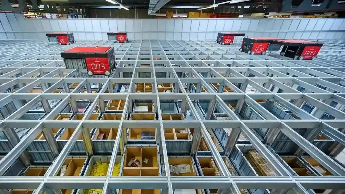
Auto Store 시방

The maximum permitted values for properties A, B and C are given below in Table1.
The floor is non-compliant if any point on the exceeds any of these values.

Property Gauge (metres) Max Value (mm)
A Flatness 1 1.2m 3.5m
2 2.3m 5.5m
B Levelness 1 1.2m 4.0m
2 2.4m 6.0m
C Datum Entire Floor 3m x 3m grid + / - 20mm

마모저항도

UK-TR34 (4th Edition)

구분 위치와 바닥용도 E F
Special 극심한 마모, 철제 물건을 바닥에서 끌면서 생기는 긁힘이나 철재 또는 단단한 수지바퀴 등의 주행으로 인한 바닥의 충격이나 마모 폐기물 처리장, 주물공장, 중공업 공장 외 0.05
AR1 매우 높은 마모, 철재 또는 단단한 수지바퀴 등의 주행으로 인한 바닥의 충격이나 마모 일반 생산공장, 창고, 물류센터 등 0.10
AR2 콘크리트 직접 마감된 소매점 바닥
높은 마모, 철재 또는 단단한 수지바퀴 등의 주행으로 인한 마모
0.20
AR3 보통의 마모, 고무 타이어의 주행으로 인한 마모
경공업공장, 일반 상업시설, 스포츠 센터 등
경공업공장, 일반 상업시설, 스포츠 센터 등 0.40

AR-TEST

*마모저항도
콘크리트 슬리브 표면이 마모에 저항하는 정도 (마모저항수치가 높을수록 표면강도가 큽니다.)
*AR-TEST
Abrasion Resistance Test는 콘크리트 바닥의 마모저항도를 측정하는 것으로 BS 8204 기준 4가지 등급의 마모저항도를 검수할 수 있습니다.
*AR-TEST 방법
1. Steel Template 을 사용하여 Digital Depth Gauge를 올려놓을 위치와 Abrasion Resistance Tester를 고정할 위치를 표시
2. Depth Gauge를 이용하여 마모를 일으킬 Wheel Track위의 8개 Points의 Data를 사전에 측정하여 Site Record Sheet에 기록
3. Abrasion Resistance Tester로 바닥에 마모를 일으킨 후 사전에 측정된 8개 Points를 재측정하여 Site Record Sheet에 기록
4. 8 Points 각각에 대한 2개의 측정값의 편차를 계산하고, 8곳 편차의 평균을 계산하여 마모저항도 시방의 통과여부를 결정